Digital techniques in high voltage measurement Voltage multimeter principle L4: potentiometers
How To Calculate Voltage In Series Parallel Circuit - IOT Wiring Diagram
Voltage tests – multimeters 101: basic operation, care and maintenance Litz wire theory & principle by litz wire manufacturer, ydk How to calculate total voltage in a series parallel circuit
Multimeter voltage dengarden connecting outlet meters sockets fused
Current meter circuit diagramMeasuring current in a circuit Tec 2 eso: measuring amps and voltsCurrent voltage measure same time circuit why ammeter.
Why you can't measure voltage and current at the same time?How to calculate voltage in series parallel circuit Measurement of voltage, frequency, phase angle by using croHow to measure current and voltage.

Phasor circuit rlc series diagram voltage current ac power draw phase impedance triangle reactive angle phasors lagging length compressor physics
How to check circuit breaker amps with multimeterVoltage current and time relationship graph of an electrical signal Voltmeter universal projects electronics simple deflection circuit input depends resistance function shown scale figure high fullMeasuring current circuit diagram.
Sparks: measuring voltage in ac circuitsDelta connection phase system line between relation voltage current figure circuit contents form Ohm's law series-parallel circuits calculationMeasuring current and volatage circuit diagram.

Multimeter voltage series potentiometers parallel two multimeters buddies
Sparks: measuring voltage on a breadboardMeasuring current and volatage circuit diagram How to use a multimeter to measure voltage, current, and resistanceGadgets projects electronics.
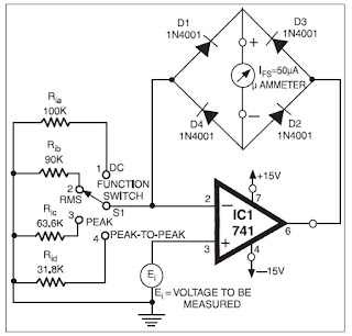
Measuring current and volatage circuit diagramVoltage series circuit calculate across resistor trades multimeters troubleshooting operation skilled maintenance advanced basic care drop Resistance measurement circuit diagramCircuit schematic for voltage measurement.

Measuring current and volatage circuit diagram
Measuring current and volatage circuit diagramHow to make measuring current circuit diagram Measuring current and volatage circuit diagramDetermining current magnitude.
Parallel series law circuits ohm circuit calculation ohms electrical simulator engineering board beginners connection learn wiring ca components online visitMeasuring current, voltage and resistance Delta connection in a 3 phase systemDigital multimeter working principle.

Induction heating principle wire coil litz theory metal current works magnetic heated melting process transformer using circuit cable field electric
Measuring current in a circuit .
.


Why you can't measure voltage and current at the same time?
gadgets projects electronics - Simple Electronic Projects

Measurement of Voltage, Frequency, Phase Angle by Using CRO - Free
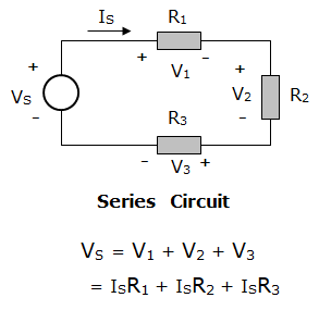
How To Calculate Total Voltage In A Series Parallel Circuit - Wiring

L4: Potentiometers | Physical Computing

Measuring Current And Volatage Circuit Diagram

Circuit schematic for voltage measurement | Download Scientific Diagram
